
A series-parallel pelvic fracture reduction robot system based on optical tracking

Technical field
This device relates to an optical tracking-based surgical robot system suitable for pelvic fracture reduction surgery.
Patent comparison
There are already a number of similar patents in this field of pelvic fracture reduction surgery, such as patent numbers CN202110569923, CN202011212195 and CN201510144378.
Patent No. CN202110569923 – A series-parallel hybrid pelvic fracture reduction robot uses a combination of a linear module and a spherical parallel mechanism to achieve the degree of freedom and stiffness required for bone needle manipulation. However, in the solution described in the patent document, the system cannot cooperate with the medical image of the pelvis to allow the robot to know the position of the pelvis to obtain positional feedback. That is, the system operates in an open-loop manner throughout the surgical operation. After completing the reset operation, you cannot perform further operations based on the errors shown in the post-reset medical images. In addition, three linear modules are used in this design to form its series part. Although the robot has a larger working space and carrying capacity, it is difficult to ensure its sterility during use because the movement characteristics of the structure make it difficult to use it as a disposable item and to cover it with a sterile film, and there is a lack of safety considerations.
Patent number CN202011212195 – A spatial hybrid pelvic fracture reduction robot is a movable pelvic fracture reduction robot. Its design principle is similar to the above-mentioned patent, both of which are series-parallel hybrid design robot structures. Likewise, the relationship between medical images and robot coordinate systems is not covered in the patent document. The problem is the same as the above-mentioned patent. The control is open-loop, making it difficult to correct the reset error and ensure the actual reset accuracy of the robot.
Patent number CN201510144378 – A six-degree-of-freedom series-parallel pelvic fracture reduction robot describes a design similar to CN202110569923. This design is different from the latter and can be wrapped with sterile membrane to ensure intraoperative sterility to ensure surgical safety. There is also the problem of coordination between accuracy feedback and medical imaging in the above-mentioned robots.
Background technology
With the increase in car ownership in society, the probability of car accidents and the number of people injured in car accidents are also increasing year by year. Pelvic fracture is a serious trauma, which is common in disasters such as car accidents and earthquakes that cause severe external impact injuries. In traditional artificial pelvic reduction surgery, the surgeon generally uses bone needles and other tools to adjust the position of the affected part of the pelvis and fix it for reduction, based on the preoperative and intraoperative X-ray images. However, in practical applications, the reduction status usually requires taking multiple X-ray images for continuous confirmation. In addition, the mapping between the images and the actual position of the pelvis is not intuitive enough and requires doctors to judge based on experience. This indirectly prolongs the operation time and inevitably brings more radiation to doctors and patients.
The steps described in this article’s robotic design are the process of adjusting and repositioning the affected area after implanting bone pins. After completing the implantation of the bone needle, the robot end effector operates the bone needle to complete the reduction task of the affected part of the pelvis. Although the several patents mentioned above can accomplish this task, because their solutions fail to show the registration relationship between the system and the medical image, it is difficult to ensure whether the robot reduction operation conforms to the actual fracture dislocation distance and post-reduction accuracy.
Program content
In view of the above-mentioned shortcomings of the existing technology, this solution designs a series-parallel robot system for pelvic fracture reduction surgery on the basis of being able to meet clinical operations. This system integrates an optical positioning system into this type of robot and describes a robot-assisted surgical process based on this system under medical image registration. After completing the registration of each coordinate system, the robot system and preoperative and intraoperative medical images are unified into the optical positioning coordinate system, so that the robot can grasp the position of the affected pelvis and accurately reset it.
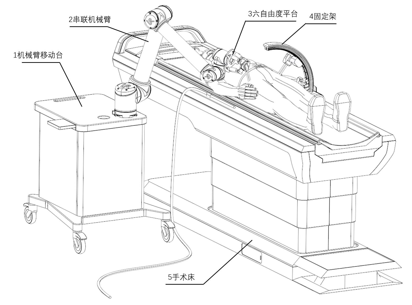
The design of the surgical robot includes an operating table, a moving robotic arm, a series robotic arm, a six-degree-of-freedom platform and a fixed frame. The series-parallel operating arm provides twelve degrees of freedom to meet the movement requirements of the reset operation. The end effector part of the robotic arm is a bone needle fixed box with a reflective ball marker, which can be captured by an optical positioning probe and feedback the location of the box. The frame slides on the operating table to stabilize the pelvic position on the non-affected side.
Description of the drawings
Figure 1 is a schematic diagram of the operation of each device of the system;
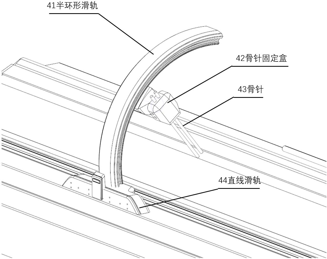
Figure 2 is a schematic diagram of the composition of the fixed frame;
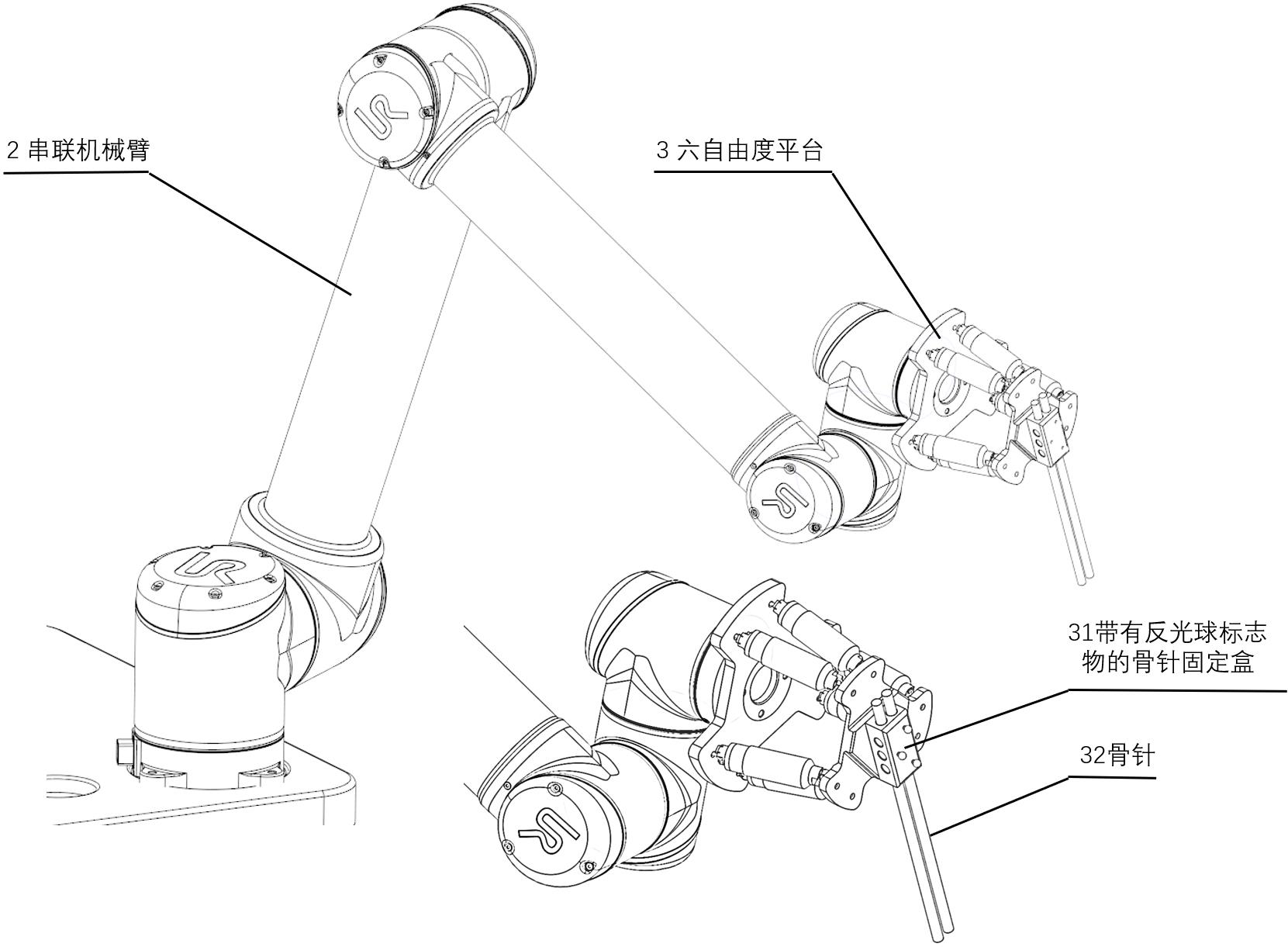
Figure 3 is a schematic structural diagram of a series-parallel robotic arm;
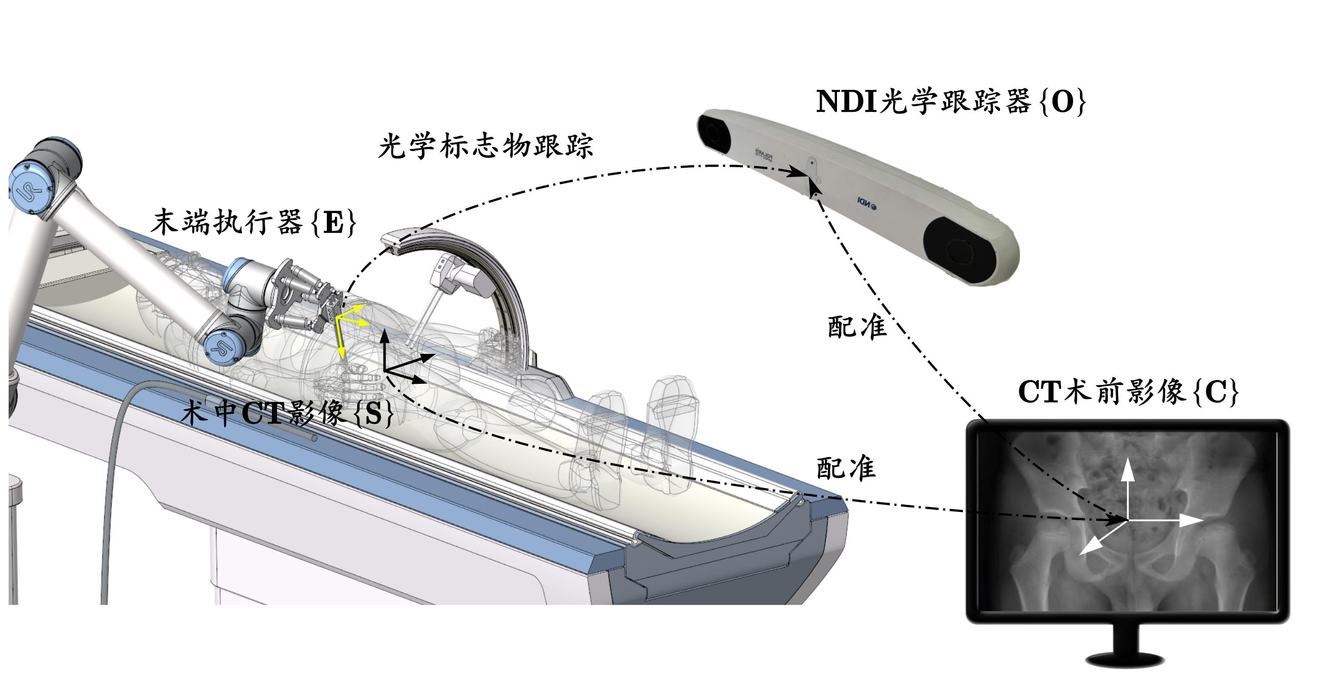
Figure 4 is a schematic diagram of the relationship between the coordinate systems of the system;
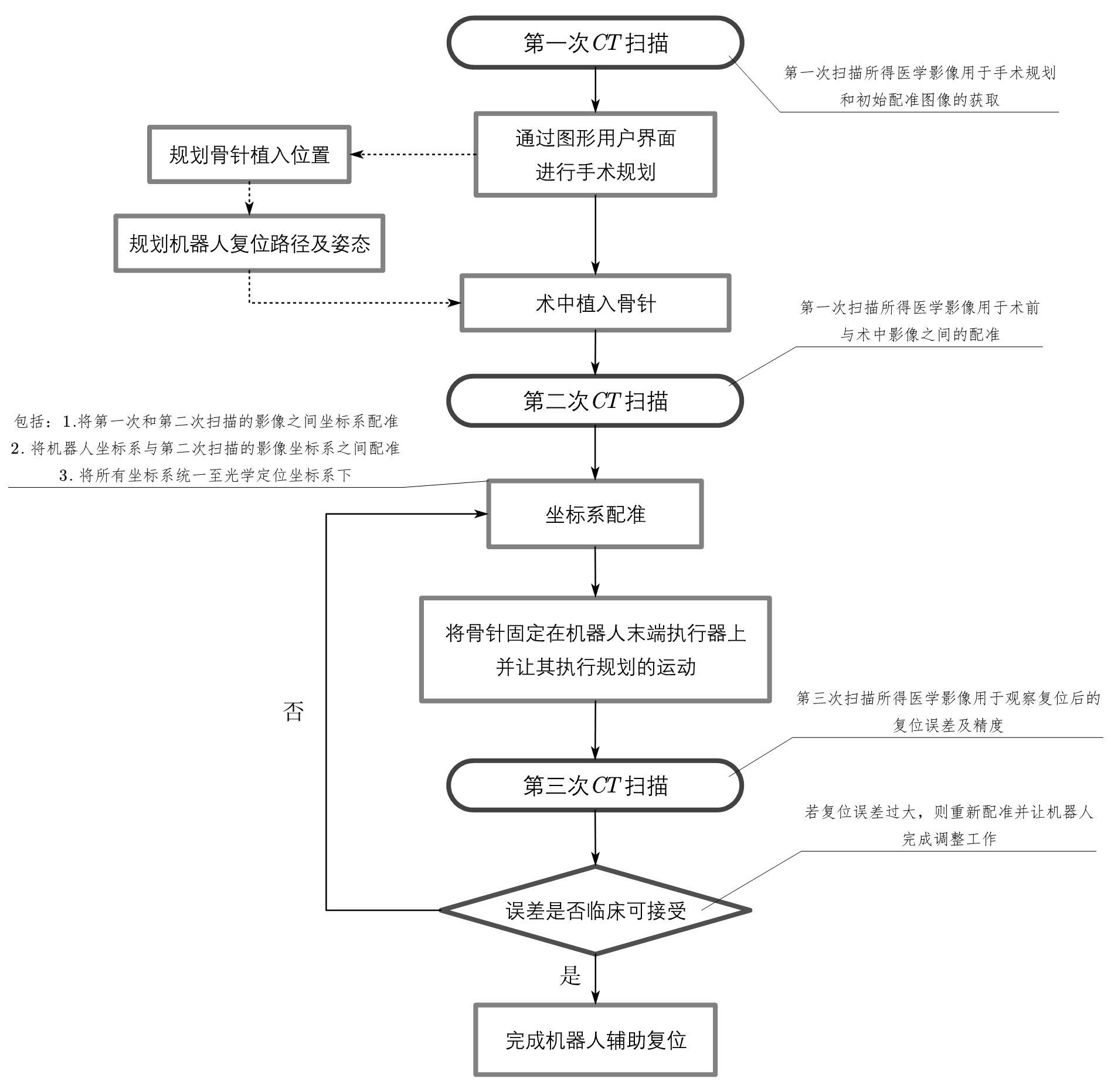
Figure 5 is the workflow diagram of the system;
Contents of the invention
Figure 1 shows the composition and working diagram of each device of the system. Before performing the reduction task, the doctor needs to fix the bone nail on the 31 bone screw fixing box with a reflective ball after implanting the bone screw. At the same time, he also needs to fix the bone screw on the non-affected side on the 42 bone screw fixing box. After completing the second CT scan, the two fixed boxes were installed on the 36-degree-of-freedom platform and the 4-fixation frame respectively. At this time, after the doctor uses the optical probe to complete the acquisition of the patient’s pelvic key points, the computer will use the algorithm to complete the direct coordinate system registration of the patient’s actual pelvic anatomy to the medical image.
During the reduction process, the 4 fixation frame is connected to the bone needle implanted in the non-affected pelvis and is fixed; the 36-degree-of-freedom platform is fixed at the end of the 2-series robotic arm, and the 31-bone needle fixation box with a reflective ball marker is fixed together with the 32-bone needle at the other end of the 36-degree-of-freedom platform. The 36-degree-of-freedom platform operates the bone needle through delicate movements to complete the path planned before surgery. The doctor then removed the 31 and 42 fixed boxes and performed a third CT scan on the patient to determine the post-reduction error. If the error is clinically unacceptable, reset it again; if it is clinically acceptable, complete the reset operation.
The series-parallel manipulator shown in Figure 3 is a type of manipulator combination with a universal structure. In this patent, the commercial UR10 collaborative manipulator (Universal Robot, USA) and the H-820 six-degree-of-freedom platform (PI, USA) are used as examples to introduce the composition and working principle of the system.
Figure 4 shows the registration relationship between each sub-coordinate system under optical tracking. The registration method is described in detail in 2.3.2 System Registration Method Introduction in the paper “System Design and Control of Ultrasound-Guided Puncture Robot for Liver Tumors” (Lin Xiaofeng. System Design and Control of Ultrasound-Guided Puncture Robot for Liver Tumors [D]. University of Chinese Academy of Sciences (Shenzhen Institutes of Advanced Technology, Chinese Academy of Sciences), 2021.).
The system described in this patent involves a total of four main coordinate systems, namely the optical positioning coordinate system {O}, the CT preoperative image coordinate system {C}, the robot’s end effector coordinate system {E}, and the patient’s intraoperative CT image coordinate system {S}. Optical positioning systems are a type of position measurement system. First, attach a wireless optical marker to the target that needs to be tracked. The shape and surface of the marker are specially processed so that the optical positioning laser generator can capture the position of this special marker in its own defined coordinate system by emitting near-infrared light. If several markers are attached at the same time to form a marker bracket, the positioning system can simultaneously feed back the position and attitude information of the bracket.
The marker bracket used in this system is a local coordinate system composed of three passive reflective balls, which is installed on the 31-bone screw fixation box. This means that the NDI optical tracker can directly obtain the position and attitude of the end effector {E}. In addition, through the iterative closest point-based registration method described in the paper, several selected landmark points on the pelvis can be used to perform registration between the intraoperative CT image {S} and the preoperative CT image {C} of the pelvis. After registration, the coordinate transformation relationship between the intraoperative CT image {S} expressed under the optical positioning coordinate system {O} and the preoperative CT image {C} can be obtained. At this time, the optical positioning coordinate system {O} can be used to represent the preoperative planned path and other coordinates defined based on the preoperative image coordinate system {C}.
In addition, since the geometric relationship of the series-parallel manipulator is fixed, the robot coordinate system itself can be mapped from the local coordinate system of the installed reflective ball to the optical positioning coordinate system {O} through the end effector coordinate system {E}. In this way, all coordinate systems can be expressed through the unified coordinate system {O}, which allows the robot to execute the movements planned in the surgical plan. It also allows the robot system to grasp the reset error and make adjustments in time during the operation.
Instructions with pictures


Leave a Reply